

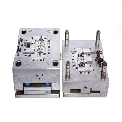




When the mold is locked, the ejector pin is squeezed flush with the parting line and all the injection pressure (~40 pounds) is applied to the sensor. This phenomenon was recorded as "zero deflection." As the mold continues to "open", the injection pressure will gradually decrease. Each time the injection pressure decreases, the sensor records an increase in deflection. Sensor calibration assumes a maximum deflection of .040 inches (1.016 mm).
Fig. 1: Assembly diagram of the installation of the mold deflection sensor Parting line mold steel Open mold When the mold steel (see "Select location") Stripping thimble diameter 5/16 inches, with 0.5 inch x 0.25 inch needle (DIN: 12 Millimeter x 5 mm needle) Spring RJG Mold Deflection Sensor Hardened Underlay Plate Mild steel mold deflection sensors are kits that include:
• A set of LynxTM mold deflection sensors (connectable to the eDART®).
• One spring, 0.5 ± 0.016 inch long, 0.48 inch diameter, 4.5 turns 0.085 inch 302 stainless steel wire.
• A hardened chassis (0.500 inches + 0/-.003 inches in diameter and 0.100 inches + .002/-.001 inches in thickness). The customer provided a thimble as shown on the drawing, and the length of the thimble was sufficient to reach the parting line and grow 0.040 inches. The customer also provides the backing plate and the required screws. Sensors and fittings can be mounted either on the fixed mold or on the moving mold.