












The purpose of mold technical drawing is to provide scientific, reliable, comprehensive and cost-effective basis for mold manufacturing. Mold injection design drawing standards are applicable to the entire process of mold development, manufacturing and maintenance.
The principles of mold injection design drawing are as follows:
① Uniformity Principle: Mold technical drawing must comply with national, industry and company standards, and the drawing process and specifications must be unified. Mold injection design engineers must not act independently or go their own way.
② Reliability Principle: Mold design drawings must provide reliable structure and accurate dimensions to ensure rapid and smooth mold manufacturing, ensure safe and reliable mold production, and achieve predetermined production life.
③ Completeness Principle: A complete set of mold drawings should include mold assembly drawings, main component drawings, ejector pin position drawings, wire cutting drawings, electrode drawings, frame opening drawings when ordering mold bases, etc. At the same time, dimensional annotations must be complete, accurate and aesthetically pleasing.
④ Efficiency Principle: In modern enterprises where mold injection design production speed is increasingly rapid, improving the speed and accuracy of mold drawing is very important. Mold design engineers must be proficient in using modern computer drawing tools for 3D and 2D mold design.
1.1 General Provisions for Injection Mold Design Drawing
1.1.1 Drawing Size Specifications, Title Blocks and Revision Blocks
(1) Drawing Frame Format and Sheet Dimensions (see Table 1-1)
For extended format drawing frame dimensions, determine according to the drawing frame dimensions one size larger than the selected basic format. For example, A2×3 drawing frame dimensions are determined according to A1 drawing frame dimensions, i.e., e is 20 (or c is 10).

(3) Title Block Instructions
① All drawings must have title blocks. Title blocks must be filled out completely, signatures must be handwritten, and computer-generated signatures are not allowed. Signatures must be full names, red pens or pencils cannot be used for signatures, and handwriting must be neat and standardized.
② Title blocks and revision blocks should be drawn at 1:1 scale according to automatically generated dimensions and must not be arbitrarily scaled. When drawing at non-1:1 scale, the title block must be scaled according to the printing ratio to ensure that the title block size never changes, i.e., the title block sizes of drawings printed at 1:1, 2:1, and 1:2 are the same.
③ All data in the title block must be clear and correct. If unclear or lacking information, fill in "?" question marks, especially for shrinkage rates.
④ If drawings are completed by multiple people, all data must be unified, including text height, font, color, etc.
⑤ The representation method for drawing scale is A:B. A is the dimension drawn on the drawing, and B is the actual dimension of the mold component. If AB, it is an enlarged scale; if the scale is unchanged, the scale is represented as 1:1. In mold injection design, try to use 1:1 scale, and when printing drawings, assembly drawings should be printed at 1:1 scale as much as possible. Component drawings should be scaled for printing according to actual needs, with the principle of clearly expressing component shapes. If enlargement or reduction is necessary during drawing, the scale selection should comply with national standard GB/T 14690-1993, see Table 1-2.
(4) Parts List Instructions
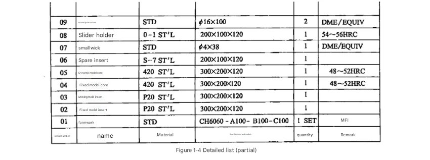
Parts lists (see Figure 1-4) are only found on assembly drawings. The parts list must detail component numbers, component names, dimensional sizes or specification models, materials, etc. Parts lists sometimes need to be listed separately and printed on A4 paper.
General requirements for filling out parts lists are as follows:
① The parts list must list all components on the assembly drawing, including templates, screws, etc.
② The "Name" column of the parts list should be filled with component names, which must be written according to standard terminology. Component standard names must follow national standards or industry standards. Unless specifically designated by the customer, Chinese names should be used throughout.
③ The "Specification Model" column includes important dimensions of components. These dimensions are usually integer dimensions of the component, and dimensions with decimal points should be rounded up to integers.
④ The "Material" column fills in component materials. Generally, externally purchased standard parts are marked "External Purchase," and special externally purchased standard parts must specify the ordering company. Self-made standard parts are marked "Self-made." Note that all components requiring processing at the company before assembly must have "Processing" added after the material, such as "H13 Processing."
⑤ The "Quantity" column fills in the quantity of the component. For easily damaged parts and difficult-to-process parts, pay attention to making (purchasing) extras. The format is as follows: "4+6." The first "4" represents the actual quantity of the component in the assembly drawing, and the second "6" represents the spare quantity. The spare quantity is determined according to actual conditions.
⑥ The "Remarks" column should fill in material heat treatment requirements. Additionally, ordered mold base and internal mold components should have "Ordered" written in the remarks column, and components with component drawings should have the component drawing number written.
⑦ Parts lists are created by design personnel using computers (automatically generated in AutoCAD) and printed, then reviewed and signed by supervisors for confirmation.
(5) Revision Block Instructions
After drawings are issued, if changes are needed, the drawings must be updated and redistributed, and the pre-revision drawings must be collected and stamped with "OBSOLETE" special stamps. Companies should establish "Design Department Technical Document Management Regulations" to make design documents controllable.
(6) Projection Methods
There are two projection methods: first-angle projection and third-angle projection, see Table 1-3. Different countries use different drawing projection methods. GB and ISO standards generally use first-angle projection.
Countries using first-angle projection include: China, Germany, France, and Russia. Countries and regions using third-angle projection include: United States, United Kingdom, Japan, and Taiwan and Hong Kong regions of China. Therefore, which projection method to use for mold injection design drawing sometimes depends on different customers.
1.1.2 Injection Mold Classification
Different categories of molds have different requirements for design drawings and mold steel materials. China has not yet classified injection mold grades. The following is the American SPI-SPE classification standard.
(1) Class 101 Molds
SPI-SPE standard, production life ≥1 million cycles, long-life precision injection molds.
① Detailed mold assembly drawings and component drawings are required.
② Minimum mold base material hardness is 280BHN (DME #2 steel/4140 steel).
③ Internal mold inserts with cavities must be hardened to 48-50HRC, and other components such as slides, wedge blocks, and pressure blocks should also be hardened. The dimensional accuracy grade of main formed components is IT5.
④ Ejector plates must have guide posts.
⑤ Slides must have wear-resistant blocks.
⑥ If necessary, fixed mold, moving mold, and slides must have temperature control systems.
⑦ For all cooling channels, it is recommended to use electroless nickel plating or use 420 stainless steel as inserts to prevent rust and facilitate cleaning.
⑧ Straight positioning blocks or tapered positioning blocks are required.
(2) Class 102 Molds
Production life 500,000-1 million cycles, high-volume production injection molds.
① Detailed mold assembly drawings and component drawings are required.
② Minimum mold base material hardness is 280BHN (DME #2 steel/4140 steel).
③ Internal mold inserts with cavities must be hardened to 48-52HRC, and other important components should also be uniformly treated. The dimensional accuracy grade of main formed components is IT6.
④ It is recommended to use straight positioning blocks or tapered positioning blocks.
⑤ The following items may or may not be needed, depending on the final production quantity. When quoting, if the following items are used, check carefully whether they are needed: a. Ejector plate guide posts; b. Slide wear-resistant blocks; c. Electroplated cooling water holes and electroplated cavities.
(3) Class 103 Molds
Life 100,000-500,000 cycles, medium-volume injection molds.
① Detailed mold assembly drawings are required.
② Minimum mold base material hardness is 165BHN (DME #1 steel/1040 steel).
③ Internal mold insert steel is P20 (28-32HRC) or high-hardness steel (36-38HRC). The dimensional accuracy grade of main formed components is IT7.
④ Other requirements depend on specific needs.
(4) Class 104 Molds
Production life 5,000-100,000 cycles, small-volume production injection molds.
① Mold structure drawings are required.
② Mold base material P20 (28-32HRC), soft steel (below 40HRC steel) or aluminum can also be used.
③ Internal mold components can use aluminum, soft steel, or other general metals. Main dimensional accuracy grades can be IT7-IT8.
④ Other requirements depend on needs.
(5) Class 105 Molds
Production life less than 500 cycles, single-piece production, prototype or test molds.
Aluminum alloy, epoxy resin, or any material can be used as long as it has sufficient strength to produce the minimum test quantity.
1.1.3 Types of Mold Injection Design Drawings and Basic Requirements
To shorten mold production cycles, designers need to provide drawings that meet various needs in the shortest time, including: mold structure simplified drawings, plastic part drawings, cavity layout drawings, mold base drawings, moving and fixed mold component sketches, mold assembly drawings, component drawings, wire cutting drawings, ejector pin layout drawings, electrode drawings, and 3D model drawings.
(1) Mold Structure Simplified Drawings
Mold structure simplified drawings are mainly used for ordering mold bases, moving and fixed mold inserts, and frame opening. Structure simplified drawings generally only show moving mold simplified drawings and one main sectional view, clearly indicating mold base specifications, frame opening dimensions, moving and fixed mold dimensions, plastic part positioning in the mold, plastic part parting conditions, and feeding positions.
Steps for drawing structure simplified drawings are as follows:
① Determine the mold's gating system based on the plastic part's shape, size, and quantity. This directly determines whether the mold base model is a two-plate mold base or three-plate mold base.
② Determine parting surface position based on plastic part shape. Priority is given to flat parting surfaces, followed by inclined parting surfaces, with arc-shaped parting surfaces as the last choice. If the parting line affects appearance, customer opinions should be sought. After determining the parting surface, consider whether the plastic part will stick to the fixed mold when opening the mold with such parting.
③ Decide which positions will be inserts. Weak structures, polishing and machining difficult structures, and exhaust difficult areas often require inserts.
④ Decide how the plastic part will be demolded. Consider whether the plastic part needs lateral core pulling, forced demolding, secondary or even multiple demolding, pneumatic demolding, push block demolding, or push plate demolding and other special demolding structures. If only ejector pins and ejector tubes are used for demolding, the position, size, and quantity of ejector pins must be considered. The demolding method of plastic parts greatly affects mold injection design structure.
⑤ When designing ejector pins, cooling water arrangement must be considered simultaneously to avoid mutual interference.
⑥ Determine cooling channel positions. Cooling channels should be placed at the bottom or side of cavities as much as possible, passing through areas with the most heat. If cooling water cannot pass directly, consider adding heat dissipation pins or using beryllium copper inserts.
⑦ Determine the size and steel materials of mold inserts. After comprehensively considering the above factors, the size of mold inserts can be determined. Insert sizes should be integers, and thickness should be standard. What steel materials to use depends on plastic type, whether plastic parts are transparent, plastic part precision, and batch size.
⑧ Determine mold base size and specification model. Based on feeding method, internal mold insert size, whether hot runner systems are used, double ejector plates, and lateral core pulling mechanisms, determine mold base size and specification model.
(2) Plastic Part Drawings
After clearly understanding customer requirements and plastic part performance, and fully considering demolding angles, tolerance fits, etc., modify customer plastic part drawings and input them into computers, cataloging them according to company standards.
(3) Cavity Layout Drawings
For some complex molds that are difficult to draw by hand, designers can draw them on computers according to supervisor instructions. Their function is the same as mold structure simplified drawings. Cavity layout drawings may not show ejector pins, support posts, springs, etc., only need to show moving and fixed mold layouts and one side view. When there are lateral core pulling mechanisms, the lateral core pulling structure must be drawn completely. Layout, pillow positions, and feeding must also be expressed. If plastic part drawings exist, they can be imported into the mold layout. If not, a rough outline and important parts can be drawn.
(4) Mold Base Drawings
For non-supplier standard mold bases or mold bases requiring frame opening processing at mold base factories, mold base drawings must be drawn. Mold base drawings are faxed to suppliers for production, so A4 paper should be used to clearly express dimensions and requirements to be processed. Standard mold base dimension parts can be omitted from annotation.
Mold base drawing contents include: Templates (fixed mold, moving mold, square iron, ejector pin fixing plate, ejector pin bottom plate, moving and fixed mold fixing plates); guide posts and guide sleeves, screws below guide posts; connecting screws between templates, positioning pins; ejector plate guide posts and guide sleeves; reset rods (springs not drawn); ejector plate limit nails or limit pull rods; ejector plate screws; mold pockets (four corner positions between each plate, including between needle plates); exhaust grooves below guide posts; lifting mold screw holes, mold code grooves; inserts, slides, tightening blocks, square positioning blocks, tapered positioning blocks, etc.; dimensions (including plan view coordinate dimensions, plate thickness, component size and quantity, precision frame dimension tolerances, lifting mold hole positions, prying mold groove dimensions); names of steel materials for each template. See Figure 1-34.
(5) Moving and Fixed Mold Component Sketches
To shorten mold making cycles, for general molds, when assembly drawings are not completed, mold component sketches can be issued first to ensure workshop material preparation, grinding reference surfaces, drilling screw holes, frame matching, and other work. Sketches only need to mark main dimensions.
(6) Mold Assembly Drawings
Mold assembly drawings are one of the main drawing forms of mold injection design departments. Mold assembly drawings should express the mold structure, assembly relationships between components, mold working principles, and technical requirements and inspection requirements for producing the mold. Assembly drawings must be drawn at 1:1 scale.
Before drawing mold assembly drawings, carefully study customer plastic part drawings and other technical requirements, and understand mold parting table requirements. If similar molds have been made before, their documentation can be referenced. Before drawing mold assembly drawings, completely accurate plastic part drawings are required. Sometimes plastic part drawings need appropriate modifications, such as adding necessary demolding angles. For tolerance requirements, tolerances need conversion, generally considering modification to shapes favorable for adding plastic in the future. When converting plastic part drawings to cavity drawings within mold bases, first multiply by shrinkage rate plus 1, then perform mirror processing (reflection), while paying attention not to place moving and fixed mold cavity drawings in wrong positions. During layout, ensure cavity drawing references are integers relative to mold base references.
Multi-cavity mold drawings must mark cavity numbers. For gears and other multi-cavity point gate molds, runners must also be marked with corresponding cavity numbers, such as CAV.No.1, CAV.No.2, etc.
Fine structures in mold assembly drawings must be enlarged for processing.
Angled ejector pin plan layout drawings (including bottom slides) must be clearly expressed with clear dimensional markings for processing convenience and to prevent interference with other components.
Hole codes must be marked on mold assembly drawings, such as support posts marked with SP and sequence numbers. A complete mold assembly drawing should have the following contents:
① Sufficient graphics to express mold construction.
② Complete and accurate dimensions.
③ Ejector pin lists (flat tops, supported ejector pins, and ejector tubes must be clearly marked, preferably auto-generated).
④ Component numbers, title blocks, parts lists, revision blocks.
⑤ Cooling water circuit axonometric diagrams, and exhaust diagrams for special cases.
⑥ Various hole positions and their codes. Common hole positions and codes are shown in Table 1-4.
Common line widths and uses in mold injection design drawings are shown in Table 1-5. Line colors vary by individual, provided here for reference only, but line colors within the same company should be unified.
Two common arrangement methods for mold assembly drawings are shown in Figure 1-5.
(7) Component Drawings
Component drawings are drawings showing component structure, size, and technical requirements, and are one of the important technical documents for company production organization. Component drawings should select the minimum number of views possible while fully and clearly expressing component shape and structure. For complex components, at least one three-dimensional view is required. Component drawing dimensions must be correct, complete, clear, and reasonable.
Technical requirements for mold component drawings: In addition to graphics and dimensions, mold component drawings must also include various codes and text descriptions in different forms. These are technical indicators proposed to ensure plastic part performance requirements, such as demolding angles, surface roughness, limits and fits, surface shape and position tolerances, and heat treatment requirements.
① Surface roughness marking
(8) Wire Cutting Drawings
Use solid lines to express wire cutting parts. Wire cutting drawings must have threading hole positions and dimensional sizes. Wire cutting drawings must mark large outline dimensions for wire cutting, which can be measured simply with calipers, gauges, etc. Complex curved outlines may not require dimensional marking.
② Wire cutting outline lines must be expressed with 1.5d thick solid lines.
(9) Ejector Pin Layout Drawings
When ejector pin quantities exceed 20 or ejector pins are too close for clear expression, or when insert ejector pins need combined processing, separate layout drawings must be drawn.
(10) Electrode Drawings
Electrode drawings must be drawn in the following cases:
① Class 101 and Class 102 molds;
② Complex and large molds.
Electrode drawings must have electrode erosion diagrams to express erosion methods and necessary measurable dimensions.
(11) 3D Model Drawings
For complex plastic parts, 3D stereoscopic drawings must be drawn using UG or Pro/E. For complex molds and molds requiring CNC machining, 3D mold drawings are required. 3D mold drawings should include at least moving and fixed mold inserts, cores, A and B plates. For molds with lateral core pulling, slide inserts and slide seats must be drawn. For molds with angled ejector pins, angled ejector pins, angled ejector pin seats, and top ejector pin fixing plates must be drawn. Except for ejector pin holes, screw holes, and sharp edge chamfers, all other shapes must be drawn in 3D models. 3D parting assembly drawing names should be consistent with 2D mold structure drawings, and 3D component drawing names should be consistent with 2D component drawings.
1.1.4 Management of Mold Injection Design Drawings
For convenient drawing management, mold drawing files must be uniformly named. Different companies use different naming methods. The following method is provided for reference.
